Warren pony truss with alternating verticals Built 1892. These beams transmit the loads to the girders.
Half Through Bridges Steelconstruction Info
Deck plate girder Built 1912 1912 Deck plate girder bridge over CSXTRR on NSRR NS -.

. Bridge Design Philosophy 4 Highway Bridges Economy of section with continuous spans Different measures for protection of bridge elements ie we dont intentionally salt railway bridges anymore Railway Bridges Simple spans are easier and faster to maintain and replace. Renovated in 2007 Built by NW Railway Pony truss bridge on 1st Street over the NS Railroad yard converted to pedestrian bridge. The plates were joined together using angles and rivets to obtain plate girders of desired size.
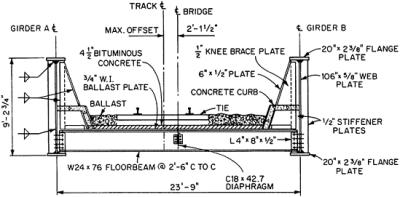
A short summary of this paper. Live loads from the trains are distributed by ties ballast and a Grade 50W steel ballast plate to rolled-steel floorbeams spaced 25 ft c to c. 3 between centerline bridge centerline track top of rail ïâ table of lifting weights description mark no.
Figure 383-3 Knee Brace for Through-Girder Bridge Through girders should be laterally braced with gusset plates or knee braces with solid webs connected to the stiffeners as shown in. Ponythrough plate girder bridge over Crooked River on Norfolk Southern Railway Open to traffic NS - CSX Overpass Lee County North Carolina Main design. The first tubular wrought iron plate girder bridge was built in 1846-47 by James Millholland for the Baltimore and Ohio Railroad.
Plate girders are usually prefabricated and the length limit is frequently set by the mode of transportation used to move the girder from the bridge. This page contains information useful to those interested in steel through girder railroad bridges. CSemi through type bridge - The deck lies in between the top and the bottom of the main load carrying members.
The girders are spaced 2375 ft c to c. Such spans preferably should contain only two main girders with the railway or roadway between them Fig. 43 Half through plate girder bridges 36.
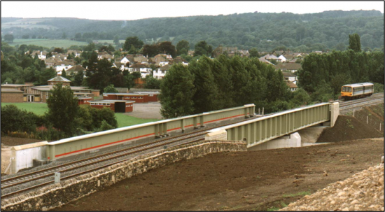
Through girder bridges are fracture critical since the loads are supported on the two through girders. Plate girder bridges are suitable for short to medium spans and may support railroads highways or other traffic. Through girders support the deck near their bottom flange.
Truss Bridge - Types History Facts and Design. So-called standard bridge types were developed by British Rail from the 1950s onwards and although there is currently only one true standard bridge type in. In contrast deck girders.
The track is on an 8 curve for which the maximum design speed is 30 mih. Maximum offset of centerline of track for centerline of bridge is 212 ft. WisDOT Bridge Manual Chapter 38 Railroad Structures January 2019 38-8.
In its most basic form a beam bridge consists of a horizontal beam that is supported at each end by piers. The new bridge is located on a straight but inclined section of rail track with the road running at an approximate skew angle of 50 to the railway. By 1950s welded plate girders replaced riveted and bolted plate girders in developed world due to their better.
Maximum offset of centerline of track for centerline of bridge is 212 ft. The girders are spaced 2375 ft c to c. In the through type truss girder bridge the roadway or railway is placed at the bottom chord level.
These combined features were in response to an exceptionally complex set of site conditions and design challenges to cross Interstate 94 in the Twin Cities. If either fails the structure fails. This through plate girder bridge has an extreme skew 64 degrees and an exceptional main span length 161 feet for its type.
Some experience of bridge design perhaps of the design of highway. For long or heavily loaded bridge spans restrictions on depth of structural system imposed by vertical clearances under a bridge generally favor use of through construction. Hell Gate Bridge a through-arch railroad bridge in New York City pictured around 19151920.
The track is on an 8 curve for which the maximum design speed is 30 mph. 1 minutePlate girders became popular in the late 1800s when they were used in construction of railroad bridges. In addition I have added all the loads to the model including a moving railroad load using the load generation function.
Maintenance and inspection costs for deck girder bridges are typically lower. Integral to TPG behavior is the knee brace connection from the girder web and top flange to the floorbeam or floor system. The AREMA Manual limits the spacing of knee braces to 12 feet maximum.
Live loads from the trains are distributed by ties ballast and a Grade 50W steel ballast plate to rolled-steel floorbeams spaced 25 ft c to c. The bracing of the top flange or lateral support of the top chord under compression is also required. How do girder bridges work.
Through girder railroad bridge design. See more ideas about bridge footbridge bridge design. In a half-through bridge the traffic is only partially inside the structural envelope there are girders or trusses either side and a deck below but the girders are not as high as the traffic envelope and thus there cannot be any bracing to the top flanges or chords.
This means that a half-through bridge is in the form of a trough ie. Through-plate girders TPGs are a common structural choice for medium span railroad bridges in particular where clearance below the structure needs to be maximized. Weight lb girder lt girder rt 113530 floorbeam panel fbp1 floorbeam panel fbp2 fbp3 floorbeam panel fbp4 knee brace kb1 380 knee brace kb2 535 knee brace kb3 560 bent curb plate bcp2 bcp4 595 bent curb plate.
Jan 28 2022 - Explore Eric Birkhausers board Bridge - Through Girder followed by 111 people on Pinterest. The term girder is often used interchangeably with beam in reference to bridge design. Note how the bridge deck cuts horizontally through the arch so some of the arch is above the deck and some below and the big abutments at either end holding the arch in place.
Concrete ponythrough girder bridge over East Twin River on 17th Street Open to traffic 1st Street Bridge Roanoke Virginia Main design. The reason I am using STAAD is to determine what the maximum loads are from the different load cases I have. Ideal for the Wintertime months these wine and white nails are quick to replicate and glimpse amazing on clean up short nails.
A deck grider bridges has multiple girders and therefore built-in redunancy. In railroad bridges spacing of the through girders should be at least 120 of the span or should be. It has a square U-shaped form.
I am designing a through girder railroad bridge and I have laid out the nodes beams girders and support conditions. The Knee Brace is defined by the.

File Design Of A Plate Girder Railroad Bridge 1913 14760875535 Jpg Wikimedia Commons
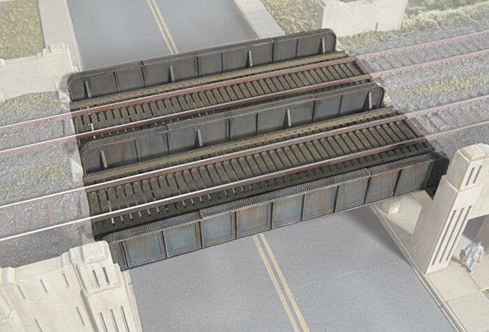
Walthers Through Plate Girder Bridge Kit Build As Single Or Double Track 933 2948

Design Of A Plate Girder Railroad Bridge 1913 14574185110 Stock Photo Alamy

Historic Bridges Bridge 27956

File Design Of A Plate Girder Railroad Bridge 1913 14757697901 Jpg Wikimedia Commons
12 9 Through Plate Girder Bridges With Floorbeams Engineering360
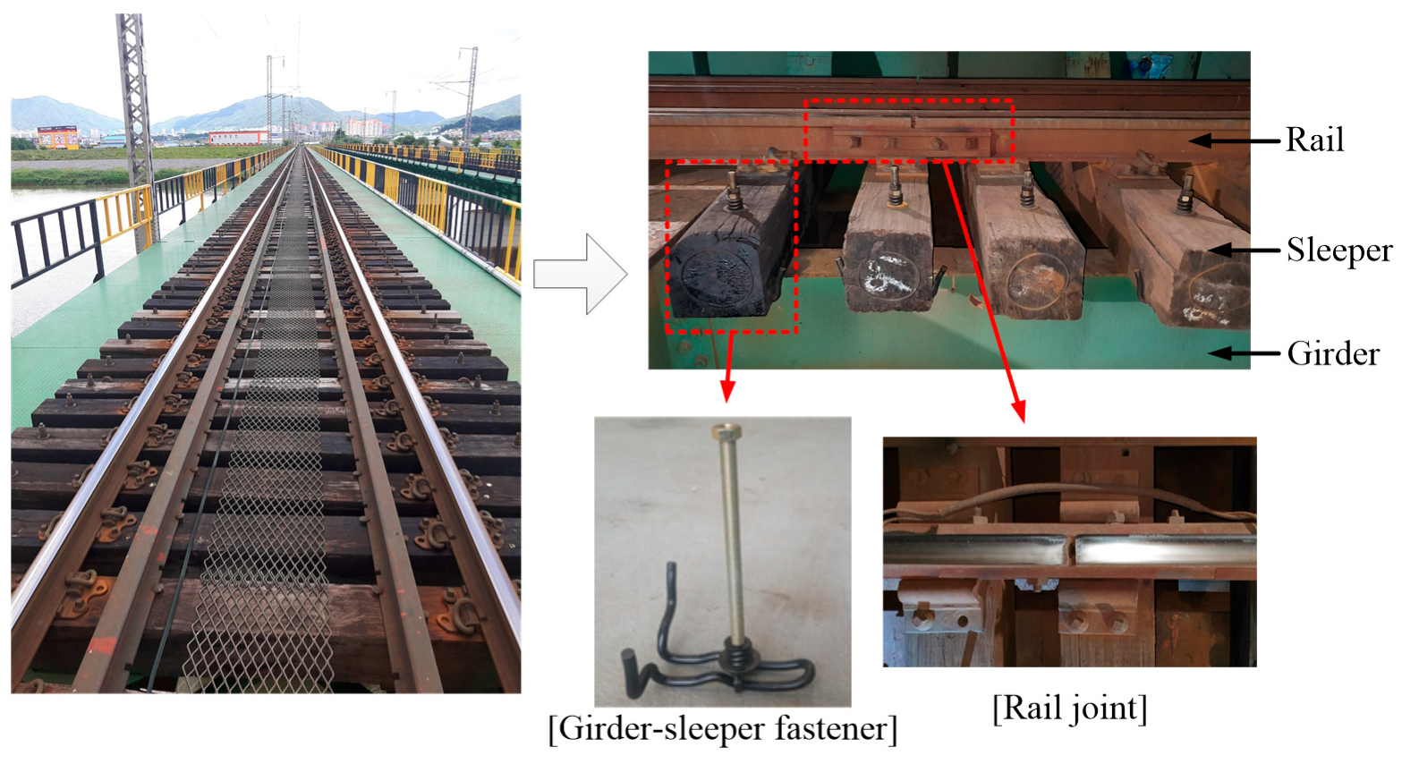
Applied Sciences Free Full Text Lateral Resistance Requirement Of Girder Sleeper Fastener For Cwr Track On An Open Deck Steel Plate Girder Bridge
Deck Bridges
0 comments
Post a Comment